When “Good Enough” Isn’t: Rethinking Lap Splices in RC Structural Walls
Executive Summary
This article examines recent experimental evidence showing that staggered lap splices—while permitted by some design standards—can significantly reduce the deformation capacity of reinforced concrete (RC) structural walls when placed near critical regions. Full-scale testing reveals that bond failure in splice zones leads to early strength degradation and drift capacities well below both seismic demand and code-based predictions. By comparing these findings with ACI and Eurocode provisions, the article highlights a key shift in modern seismic design philosophy: prioritizing ductility by avoiding lap splices in plastic hinge regions altogether.
When “Good Enough” Isn’t: Rethinking Lap Splices in RC Structural Walls
Reinforced concrete (RC) walls are often the quiet workhorses of seismic design—expected to flex, dissipate energy, and keep buildings standing when earthquakes strike. A seemingly small detailing choice, however, can have an outsized impact on their performance: the use and placement of lap splices.
A recent experimental study On estimating the drift capacity of reinforced concrete walls with lap splices at their bases sheds new light on this issue, focusing on staggered lap splices in RC structural walls. While current design standards permit their use—even near critical regions like the base of walls—the findings suggest that this long-standing practice may not be as safe as previously assumed.
Let’s unpack what’s going on, starting simple and gradually diving into the mechanics.
The Basics: What Are Lap Splices and Why Do They Matter?
In reinforced concrete, steel bars carry tension while concrete handles compression. When a bar needs to be extended, engineers often overlap two bars—this overlap is called a lap splice. The idea is straightforward: forces transfer from one bar to the other through the surrounding concrete via bond stress.
There are two common configurations:
- Non-staggered splices: all bars splice at the same section
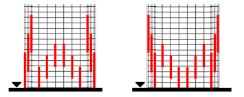
- Staggered splices: splices are offset so not all bars overlap at once
Modern standards (like NZS 3101) encourage staggering to avoid creating a weak plane. On paper, this seems like a sensible compromise between constructability and performance.
But earthquakes don’t care about convenience—they expose the weakest link.
The Problem: Earthquake Damage Tells a Different Story
Field observations from major earthquakes (Chile 2010, Taiwan 2016, Turkey 2023) consistently show severe damage concentrated at lap splice regions in RC walls.
This isn’t just anecdotal. It reflects a deeper issue:
Lap splices may be strong enough to carry load—but not ductile enough to sustain large deformations.
In seismic engineering, ductility—the ability to deform without losing strength—is critical. Structures don’t just need to resist forces; they need to absorb and survive them.
The Experiment: Full-Scale Testing of RC Walls
To investigate this, researchers tested two full-scale RC wall specimens:
- Height: ~8.1 m
- Shear span: 6.45 m
- Flexure-dominated behavior (typical for slender walls)
- Staggered lap splices near the foundation (a critical region)
The only difference between the two walls (W1 and W2) was how the splices were arranged.
Both were subjected to cyclic lateral loading to simulate earthquake effects.
What Happened: Early Failure and Limited Drift Capacity
Here’s where things get interesting.
- Both walls yielded at ~0.7% drift
- Splice failure began shortly after:
- W1: ~1.0% drift
- W2: ~1.25% drift
- Ultimate drift capacities:
- W1: 1.6%
- W2: 1.3%
These are low values for modern seismic design.
Why is this concerning?
Because expected earthquake demands are higher.
The Reality Check: Demand vs Capacity
Using established seismic estimation methods, a plausible drift demand for RC wall buildings is about:
- ~2.3% drift
Compare that to the tested capacities:
| Wall | Drift Capacity |
|---|---|
| W1 | 1.6% |
| W2 | 1.3% |
Both fall short.
This means that, under realistic earthquake conditions, these walls would likely experience significant damage or failure.
The Deeper Issue: Design Standards Overestimate Performance
Here’s where the study becomes especially critical for engineers.
Two common approaches were used to predict drift capacity:
- Design standard (NZS 3101) → ~3.2%
- Assessment method (C5 guidelines) → ~2.6%
Both significantly overestimated actual performance.
Why the discrepancy?
Because both methods assume:
- Strains are evenly distributed along a plastic hinge region
- Bond between steel and concrete degrades gradually
But the experiments showed something very different:
Deformations localized at splice regions, and bond failure occurred suddenly and early.
In other words, the real behavior is far more brittle and concentrated than models assume.
Failure Mechanism: What Actually Goes Wrong?
The sequence of failure was consistent:
- Outer splices fail first (bond failure)
- Load shifts inward
- Inner splices fail
- Rapid degradation in strength
This cascading failure is dangerous because:
- It reduces redundancy
- It accelerates strength loss
- It limits energy dissipation
A Misleading Safety Net: “Rocking” Behavior
There’s a common argument that after splice failure, walls may still survive through rocking (rotating at the base).
The study challenges this assumption.
In one specimen:
- The “rocking plane” formed 1 meter above the foundation, not at the base
This unpredictability means:
- The structure may not behave as intended
- Load paths become uncertain
- Collapse mechanisms are harder to control
Conclusion: rocking is not a reliable fallback mechanism.
Key Insight: Location Matters More Than Configuration
The study reinforces a critical principle:
It’s not just how you splice—it’s where you splice.
Even properly detailed, code-compliant staggered splices performed poorly when placed near:
- Plastic hinge regions
- Zones of expected yielding
Practical Implications for Design
The findings point toward a clear shift in best practice:
1. Avoid lap splices in critical regions
Especially near:
- Foundations
- Plastic hinge zones
2. Prefer continuous reinforcement
This eliminates bond transfer uncertainty altogether.
3. Use alternative connection methods
If splicing is unavoidable:
- Mechanical couplers
- Welded connections
4. Rethink assessment models
Existing buildings with lap splices may be less ductile than assumed, requiring:
- More conservative evaluations
- Possible retrofitting
How Do These Findings Stack Up Against ACI and Eurocode?
The experimental results expose a core issue: modern design standards may overestimate deformation capacity when lap splices are present in critical regions. To understand the implications, we compare how different codes treat lap splices in seismic RC walls—from philosophy to mechanics.
1) Big Picture: Philosophical Differences
NZS 3101 (Context of the Study)
- Allows staggered lap splices in plastic hinge regions
- Focuses on strength development (yielding)
- Limited explicit treatment of post-yield deformability
👉 Result: Code-compliant walls failed below expected drift capacity
American Concrete Institute — ACI 318
- Restricts lap splices in seismic hinge zones
- Requires:
- No splices in boundary elements where yielding is expected
- Use of mechanical couplers or continuous bars
- Emphasizes:
- Ductility
- Confinement
- Controlled plastic hinging
👉 Philosophy: Avoid the problem entirely
Eurocode 8 (EN 1998-1)
- Discourages or prohibits splices in critical regions
- Requires:
- Splices placed away from plastic hinges
- Enhanced detailing if unavoidable
- Emphasizes:
- Capacity design
- Ductile failure modes
👉 Philosophy: Preserve ductility through detailing control
2) Critical Comparison: Splice Location Rules
| Code | Splices in Plastic Hinge Region? | Approach |
|---|---|---|
| NZS 3101 | Allowed (if staggered) | Strength-based |
| ACI 318 | Prohibited | Ductility-first |
| Eurocode 8 | Generally prohibited | Capacity design |
Insight: Experimental results validate the stricter ACI and Eurocode stance.
3) Drift Capacity: Prediction vs Reality
From experiments:
- Measured: 1.3%–1.6%
- NZS prediction: ~3.2%
- C5 assessment: ~2.6%
ACI / Eurocode approach:
Rather than modeling splice behavior in hinge zones, they:
- Eliminate splices from those regions
- Assume:
- Continuous reinforcement
- Stable plastic hinging
- Distributed curvature
This avoids the strain localization error seen in NZ predictions.
4) Core Technical Issue: Bond vs Ductility
NZ assumption:
- Splices develop yield strength
- Bond degrades gradually
- Strains are distributed
Experimental reality:
- Bond failure at ~1% drift
- Strains localize
- Rapid strength degradation
ACI / Eurocode response:
- Treat lap splices as potentially brittle
- Avoid relying on:
- Bond under cyclic loading
- Post-yield splice behavior
Recognizes bond-slip as non-ductile and unreliable
5) Plastic Hinge Modeling Assumptions
NZ / C5:
- Drift ∼ θₚ · Lₚ
- Assumes uniform strain distribution
Observed behavior:
- Deformation concentrates at splice zones
- Effective hinge length shrinks
- Leads to:
- Higher local strains
- Early failure
ACI / Eurocode implication:
- By avoiding splices in hinge zones:
- Plastic hinges form in continuous steel
- Modeling assumptions remain valid
6) Failure Modes: Controlled vs Uncontrolled
NZ-compliant walls:
- Governed by:
- Bond failure
- Bar slip
- Progressive collapse:
- Outer → inner splice failure
Brittle and uncontrolled
ACI / Eurocode design:
- Governed by:
- Steel yielding
- Confined concrete crushing
- Behavior:
- Gradual
- Energy dissipating
Ductile and controlled
7) The “Rocking” Misconception
Assumption:
- Walls may survive via rocking after splice failure
Experimental finding:
- Rocking plane formed above foundation, not at base
ACI / Eurocode philosophy:
- Do not rely on secondary mechanisms
- Ensure behavior is:
- Predictable
- Designed
Aligns with capacity design principles
8) Bottom Line: Who Got It Right?
The experimental evidence strongly supports:
- ACI 318
- Eurocode 8
Why?
They:
- Anticipate bond-related brittleness
- Eliminate reliance on splices in critical zones
- Preserve ductile mechanisms
Final Engineering Takeaway
This comparison highlights a gap between code assumptions and physical behavior:
- NZS approach: permits a detail that behaves non-ductile under cyclic loading
- ACI / Eurocode: eliminate that uncertainty
Bond-controlled mechanisms cannot be relied upon in plastic hinge regions—even if they satisfy strength requirements.
Final Takeaway
Lap splices have been used for over a century, and in many contexts, they work just fine. But in seismic applications—particularly in RC structural walls—their behavior is more nuanced and potentially hazardous than design codes currently reflect.
This study makes one thing clear:
Code compliance does not guarantee seismic resilience.
As performance-based design continues to evolve, details like lap splice placement—once considered routine—deserve much closer scrutiny.